 WAFU
WAFU
Truly Waterproof and Dustproof ? Start with Airtightness Testing ! Wireless Bridge Enclosure Leak Testing Case
1. Testing Requirements
A wireless bridge manufacturer found that the high rework rate caused by water ingress due to poor enclosure sealing was becoming a serious issue during mass production. They urgently needed an efficient and accurate air leak testing solution. The testing equipment was required to perform fast, non‑destructive leak tests on every finished enclosure, with precision meeting the specified air tightness criteria – i.e., a pressure drop of less than 150 Pa over a 10‑second hold time under negative pressure of –100 kPa and positive pressure of 300 kPa.
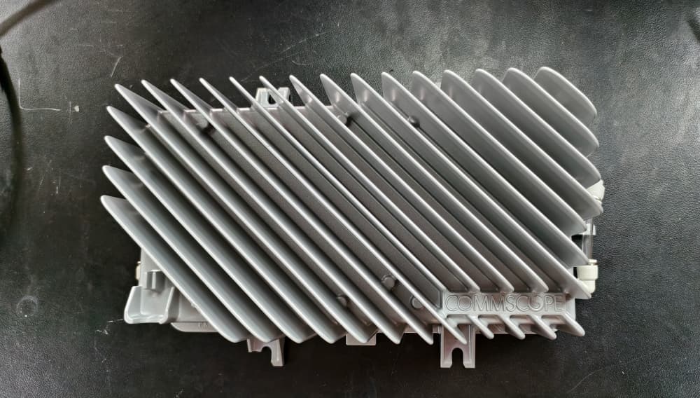 Figure 1: Wireless bridge enclosure to be tested
2. Analysis of Testing Challenges
Although the wireless bridge enclosure has a relatively simple overall structure, several factors can affect testing accuracy and stability during the actual process.
- The enclosure is large in size and has a considerable internal volume, which requires high inflation stability and longer testing time.
- The product usually has multiple openings, so proper sealing must be arranged according to the product structure.
3. Fixture Design Solution
Based on the structural characteristics of the wireless bridge enclosure, a custom‑designed testing fixture was adopted to achieve rapid positioning, automatic sealing, and stable testing. The entire fixture consists of three main parts: a sealing filling jig, a pressing assembly, and a plugging assembly.
3.1 Sealing Filling Jig
To perform a complete air leak test on the wireless bridge enclosure, the product must first be sealed. Due to its large volume, a filling jig was designed to reduce the internal cavity volume, thereby shortening test time and improving efficiency.
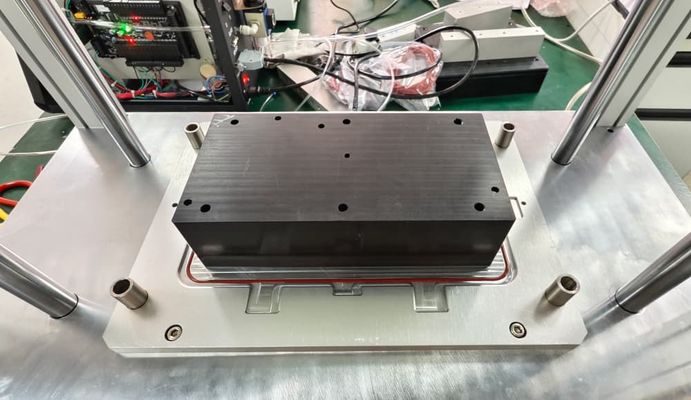 Figure 2: Sealing filling jig
3.2 Pressing Assembly
A pressing assembly is set directly above the fixture base plate, driven by a cylinder to move vertically. When the test is started, the fixture presses down to ensure that the product does not leak due to pressure changes during testing. Since the wireless bridge enclosure is already painted, a soft rubber pad is installed on the fixture to prevent damage to the product.
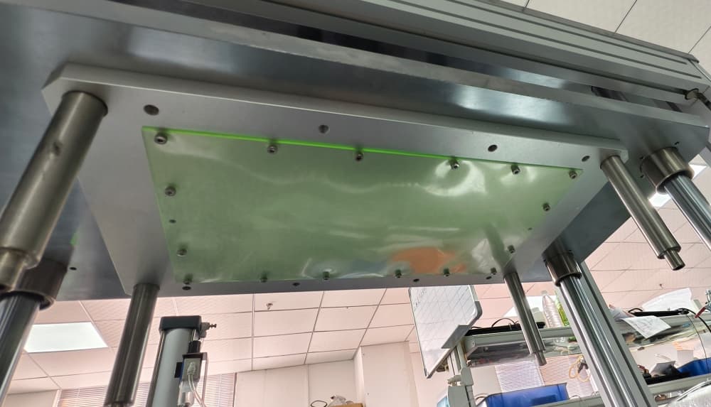 Figure 3: Pressing assembly
3.3 Plugging Assembly
There is an opening on each of the left and right sides of the wireless bridge enclosure. A conventional sealing method would require two side‑push units to block these openings. However, since both openings are standard threaded ports, a single custom sealing plug was designed. The plug is equipped with a silicone sealing ring to ensure a tight seal. This eliminates the need for two additional side‑push units, reduces the overall fixture size, saves floor space, and lowers costs.
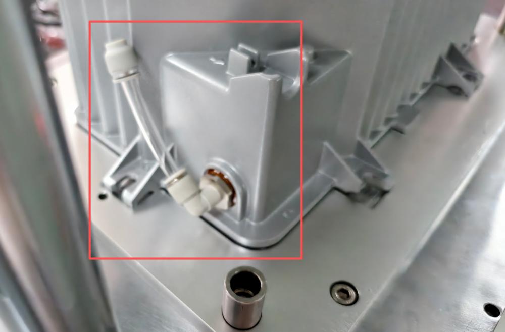 Figure 4: Right‑side plugging assembly
4. Testing Process
Step 1: Loading – The operator places the wireless bridge enclosure into the station; the jig provides self‑alignment.
Step 2: Clamping and plugging – The operator manually seals the left and right openings, then presses the start button. The pressing assembly automatically moves down to secure the enclosure.
Step 3: Inflation and measurement – The leak tester injects compressed air at 300 kPa (positive pressure) / applies a vacuum of –100 kPa (negative pressure) into the enclosure cavity through the inflation port. After reaching the set time, the inflation valve is closed and the hold phase begins. The tester uses a high‑precision pressure sensor to monitor pressure changes in real time. After 15 seconds of holding, the pressure drop is calculated.
Step 4: Judgment and output – If the pressure drop is less than 100 Pa, the product is accepted; otherwise, it is rejected. The test result is displayed on the instrument screen and can be uploaded to the production management system via the communication interface.
Step 5: Unloading – After the test, the pressing assembly retracts. The operator removes the left and right plugs, takes out the enclosure, and proceeds to the next test.
5. Results
The final deliverable was a positive/negative pressure integrated dedicated air leak tester for wireless bridge enclosures, which uses the direct pressure method. After being deployed on the production line, the equipment met the manufacturer’s requirements for test speed and efficiency, effectively solving the enclosure sealing inspection challenge and providing reliable quality assurance for product shipment.
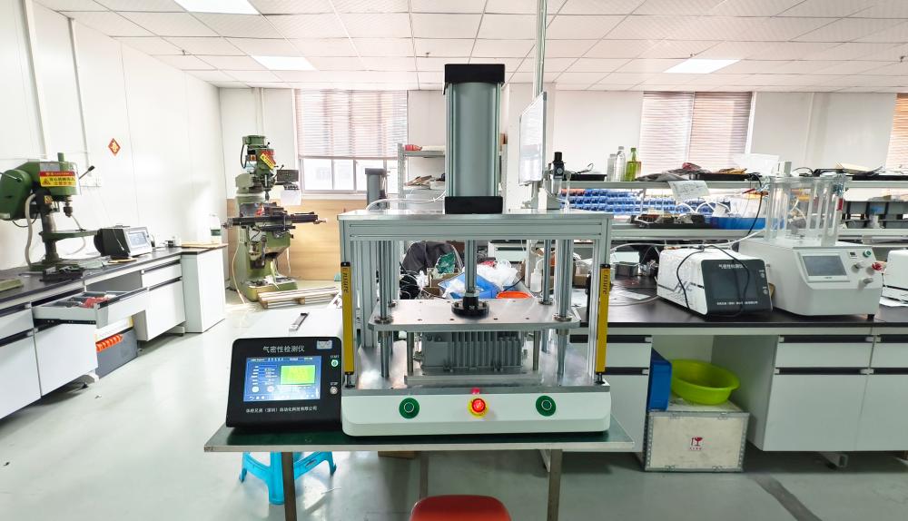 Figure 5: Positive/negative pressure integrated dedicated air leak tester for wireless bridge enclosures